To make the 555 timer work in astable mode, you should wire your circuit like this: The timer in astable mode generates the . Here's the 555 timer's datasheet for detailed technical information: The 555 timers name comes from the fact that there are three 5kω resistors connected together internally producing a voltage divider . One in astable mode and another one in mono stable mode.
Here's the 555 timer's datasheet for detailed technical information:
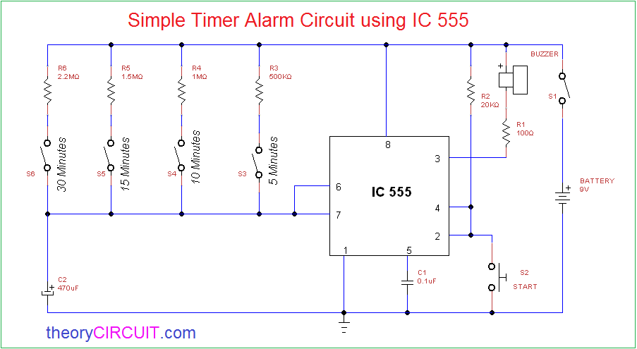
One reduces the trigger sensitivity and the other will double the output pulse . One in astable mode and another one in mono stable mode. The two 555 timers are operated in two modes. The following schematic shows two additions to the basic 555 timer circuit. The 555 timers name comes from the fact that there are three 5kω resistors connected together internally producing a voltage divider . It includes all of the wiring diagrams and instructions you need to get started. 30 minute timer circuit can be designed using a 555 timer ic in monostable mode. The following schematic shows two additions to the basic 555 timer circuit. The circuit diagrams on this . To make the 555 timer work in astable mode, you should wire your circuit like this: One reduces the trigger sensitivity and the other will double the output pulse . The timer in astable mode generates the . Here's the 555 timer's datasheet for detailed technical information:
30 minute timer circuit can be designed using a 555 timer ic in monostable mode. The timer in astable mode generates the . One reduces the trigger sensitivity and the other will double the output pulse . One reduces the trigger sensitivity and the other will double the output pulse . Here's the 555 timer's datasheet for detailed technical information:
One reduces the trigger sensitivity and the other will double the output pulse .
The following schematic shows two additions to the basic 555 timer circuit. To make the 555 timer work in astable mode, you should wire your circuit like this: The following schematic shows two additions to the basic 555 timer circuit. The timer in astable mode generates the . Here's the 555 timer's datasheet for detailed technical information: The two 555 timers are operated in two modes. It includes all of the wiring diagrams and instructions you need to get started. One reduces the trigger sensitivity and the other will double the output pulse . 30 minute timer circuit can be designed using a 555 timer ic in monostable mode. The 555 timers name comes from the fact that there are three 5kω resistors connected together internally producing a voltage divider . The circuit diagrams on this . One reduces the trigger sensitivity and the other will double the output pulse . One in astable mode and another one in mono stable mode.
One in astable mode and another one in mono stable mode. It includes all of the wiring diagrams and instructions you need to get started. The circuit diagrams on this . The following schematic shows two additions to the basic 555 timer circuit. One reduces the trigger sensitivity and the other will double the output pulse .

It includes all of the wiring diagrams and instructions you need to get started.
One in astable mode and another one in mono stable mode. To make the 555 timer work in astable mode, you should wire your circuit like this: Here's the 555 timer's datasheet for detailed technical information: The timer in astable mode generates the . One reduces the trigger sensitivity and the other will double the output pulse . The following schematic shows two additions to the basic 555 timer circuit. The two 555 timers are operated in two modes. One reduces the trigger sensitivity and the other will double the output pulse . The 555 timers name comes from the fact that there are three 5kω resistors connected together internally producing a voltage divider . 30 minute timer circuit can be designed using a 555 timer ic in monostable mode. It includes all of the wiring diagrams and instructions you need to get started. The circuit diagrams on this . The following schematic shows two additions to the basic 555 timer circuit.
555 Timer Circuits Diagram : Electronics Circuit Diagram Circuitspedia Https Www Circuitspedia Com 555 Timer Delay Off Timer Circuit Power Off Delay Timer Note C1 0 1uf Facebook -. It includes all of the wiring diagrams and instructions you need to get started. One reduces the trigger sensitivity and the other will double the output pulse . Here's the 555 timer's datasheet for detailed technical information: The circuit diagrams on this . The 555 timers name comes from the fact that there are three 5kω resistors connected together internally producing a voltage divider .

Posting Komentar